Point at Coordinate
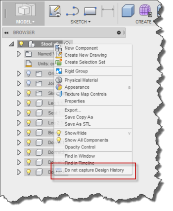
It’s possible, but not very easy, to create a construction point at a specific XYZ coordinate in Fusion 360. The process is also slightly different depending on if you’re working with a parametric model or not. First, let’s look at the process when working with a direct edit model. You define if you’re in parametric mode or not by using the “Capture design history” switch, as shown below.
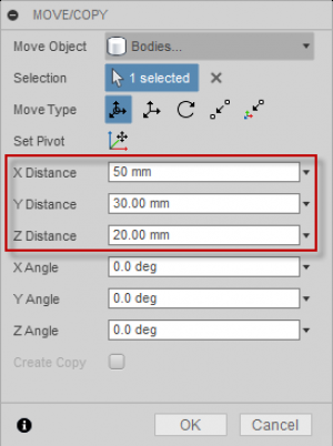
When not capturing design history, a construction point can exist anywhere in space and does not have any relationship dependency on any other geometry. However, Fusion 360 doesn’t support a command that let’s you specify the location. Instead, you have to first create a point relative to some existing geometry, the base origin point is convenient. Then you can use the Move/Copy command to move the point to the desired location, since the Move/Copy command does support the entering of coordinates. That works but is very tedious.
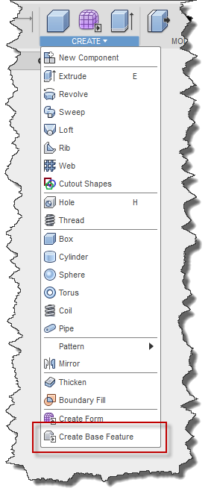
To create a construction point at any location within a parametric model is more difficult. When working in a parametric model, all construction points are dependent on other geometry and can’t exist anywhere in space so it’s not possible to position a point at an arbitrary X, Y, Z location. In a parametric model, you’re limited to the creation methods that Fusion 360 provides. However, there is a way to work around this by using something called a “Base Feature”. A base feature lets you create an “island” of direct edit data within your parametric design, so it ends up being the same workflow as in a direct modeling design, except that you also need to first create a base feature, as shown below.
Once a base feature is created, the workflow is the same as the direct edit model described above.
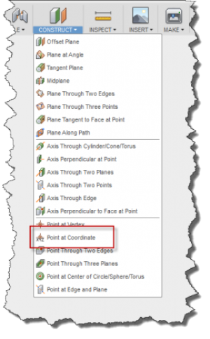
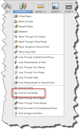
But that’s a lot of work to create a construction point at a desired XYZ location, and especially if you have several points to create. That’s the reason for this little app. Once installed, it adds a new button to the CONSTRUCT menu for the Point at Coordinate command, as shown below.
When you run the command in a direct modeling design, the dialog on the left is displayed and when you’re in a parametric design, the dialog on the right is displayed.
The “X Position”, “Y Position”, and “Z Position” fields are the X, Y, and Z values where the construction point will be created. You can use any valid expression when specifying these values, including the use of parameter names. For example, if you have a parameter named Length you can use “Length/2”. The default units are whatever the current design units are. But you can also override that by specifying the units. For example “3 in” will be interpreted as 3 inches. Whatever you use as input, it’s important to understand the point doesn’t remember this relationship so that if you use a parameter name and then later change the parameter value, the point will not move.
When the command is run in a parametric design, the “Base feature” drop-down at the top of the dialog is displayed because points at an arbitrary location must be created within a base feature when working in a parametric design This lets you specify which base feature they’ll be created in. If there isn’t an existing base feature, a new one will be created and that will be the default base feature when you run the command again, although you have the option of choosing any existing base feature.b
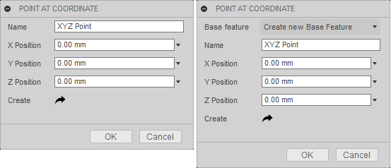
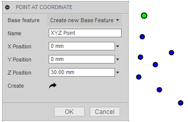
Using the “Name” field you can specify what the name of the new construction point will be. The default is “XYZ Point” but sometimes, depending on how you’re going to use the point, it can be useful to name it so you can easily identify which one is which when looking at the browser. Once the name and positions are defined you can click the OK button to create and finish the command. However, you can also click the “Create” button to specify the point but remain in the command so you can continue to create additional points. The points created when clicking the “Create” button are just temporary points until you click the OK button. Clicking “Cancel” will terminate everything since the command was started.
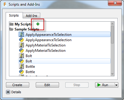
To use the add-in just unpack the downloaded zip file anywhere on your computer. Run the “Scripts and Add-Ins” command and click the green “+”, as shown below. Browse to the location where you unpacked the zip file and choose the PointAtCoord folder. You’ll only need to do this once because Fusion will remember it for subsequent sessions.
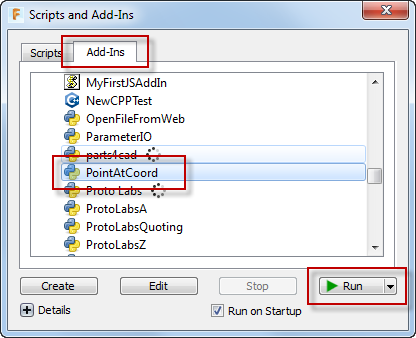
You can either shut down and restart Fusion to make the command available, or while in the same session you can start the add-in. This is only needed when first enabling the add-in because it will load automatically in subsequent sessions of Fusion. To start the add-in, choose the “Add-Ins” tab on the “Scripts and Add-Ins” dialog, select the “PointAtCoord” add-in from the list, and click the “Run” button, as shown below.
If you’ve successfully installed and enabled the add-in, you’ll see the Point at Coordinate command in the CONSTRUCT menu, as shown below.
Ekins Solutions LLC provides this program “AS IS” and with all faults. Ekins Solutions LLC disclaims any implied warranty of merchantability or fitness for a particular use.
Ekins Solutions LLC does not warrant that the operation of the program will be uninterrupted or error free.

