Nifty Slicer
For a few years I’ve wanted to try a manufacturing technique where I would slice up a CAD model into layers that are the thickness of sheet stock, (in my case it is solid core plywood), and then machine the slices and stack them up to re-create the original design. I didn’t have easy access to a CNC mill at the time so it remained an unproven idea. A while ago I got access to a Handibot CNC router and tested my idea. Below is the first result of that experiment.
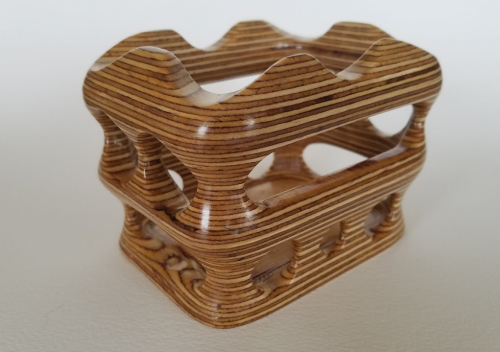
This Nifty Slicer utility came about from my need to slice up a model and orient the slices in a way that I could create tool paths. You can read more about that experience and the process in general, in my blog post about “Subadditive” manufacturing.
Command Inputs
When the Nifty Slicer command is run, the dialog shown below will be displayed where the inputs are described below.
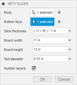
Body – The body to be sliced.
Bottom face – A planar face on the body that is the bottom face. This defines the orientation of the slicing plane.
Slice thickness – The thickness of each slice. If you have a parameter named “Thickness” or “thickness” in the design, it will use that as the default value.
Board width – The width of the board stock that you’ll be machining from. This is used to specify the size of area the slices will be laid out on.
Board height – The height of board stock that you’ll be machining from. This is used to specify the size of the area the slices will be laid out on.
Tool diameter – This is the diameter of the tool that you’ll be using to machine the slices. This is used to determine an offset between each slice as they are laid out.
Number parts – Specifies if layer numbers should be added to the slices or not.
Command Results
The add-in creates two outputs of the sliced model; the stacked slices and the laid out slices on the stock board. An example of the result is displayed below. Notice how some slices have been flipped so they are in the correct orientation to be machined. The flipping is done automatically. The original body remains unaffected.
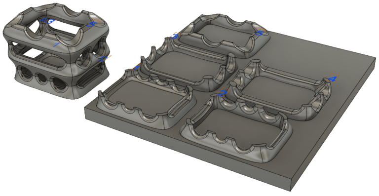
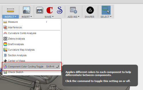
It’s much easier to visualize the result if you use the Component Color Cycling Toggle command to change all of the components to different colors.
Now it’s easy to visually match the layers in the model to those on the sheet. You can also see the numbers that were created that allow you to match up the slices to where they are in the model. This is useful when you have large models. You can print out a top view of the sheet and then as they are being cut out, label each of the pieces so you know the order they will be need be stacked.
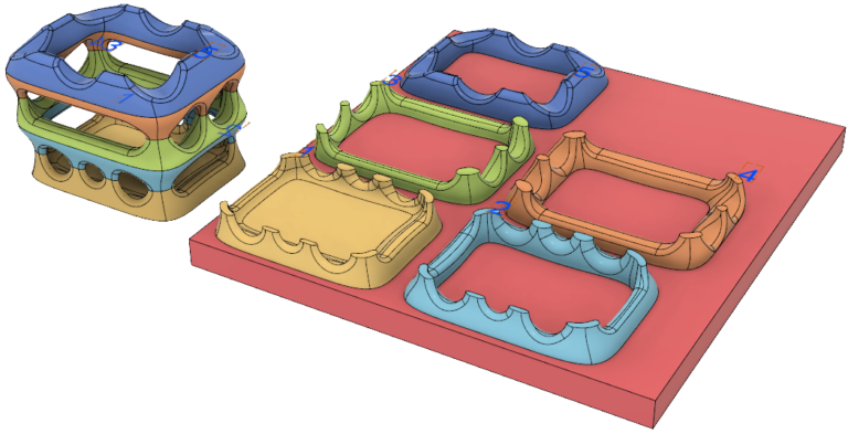
How the slices are laid out on the sheet is very simple. It should definitely be considered a layout and not nesting. It places the first slice onto the corner of the sheet, offset by the tool diameter, and then places the next layer beside it, offset by twice the tool diameter. It moves up to the next row when a slice won’t fit on the current row. The position of the next row is defined by the tallest slice in the previous row. This works great for rectangular shaped parts but for other parts, it’s not the best solution. Below is an example of slicing a larger non-rectangular model. You can see there is a lot of wasted room between the parts and the parts don’t fit on the sheet.
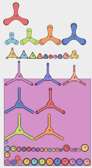
Each slice is a separate component so you can manually rearrange them on the sheet any way you would like. They aren’t constrained in any way, but if you switch to a top view, you can drag them around and they will stay on the same Z plane or you can use the Move command to move and/or rotate them. Below is the result after some manual nesting where all of the parts and even one additional large part was added and they are able to fit on the sheet.

Preparing the Model
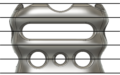
The add-in, and what it does is conceptually fairly simple. The hard part is building a model that will result in slices that can be machined using 3-axis CNC. There are two basic rules when building the model; model relative to the slice thickness and avoid undercuts. The picture below helps to illustrate both of these concepts. It’s the previous model, where I’ve drawn lines to indicate the layer thickness, which is based on the board thickness. Within each layer, the angle of all of the faces either slope in or out. Some more detail is given in my blog post for Sub-additive manufacturing.
Installing the Add-In
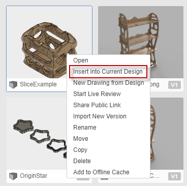
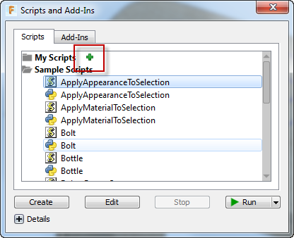
To use the add-in just unpack the downloaded zip file anywhere on your computer. Run the “Scripts and Add-Ins” command and click the green “+”, as shown below. Browse to the location where you unpacked the zip file and choose the SliceItUp folder. You’ll only need to do this once because Fusion will remember it for subsequent sessions.
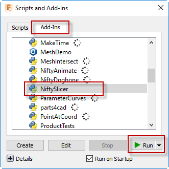
You can either shut down and restart Fusion to make the command available, or while in the same session you can start the add-in. This is only needed when first enabling the add-in because it will load automatically in subsequent sessions of Fusion. To start the add-in, choose the “Add-Ins” tab on the “Scripts and Add-Ins” dialog, select the “NiftySlicer” add-in from the list, and click the “Run” button, as shown below.
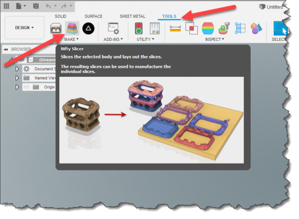
If you’ve successfully installed and enabled the add-in, you’ll see the Nifty Slicer command in the MAKE panel under the TOOLS tab, as shown below.
Ekins Solutions LLC provides this program “AS IS” and with all faults. Ekins Solutions LLC disclaims any implied warranty of merchantability or fitness for a particular use.
Ekins Solutions LLC does not warrant that the operation of the program will be uninterrupted or error-free.
