I thought of a technique for creating interesting shaped wooden models a few years ago but didn’t have the equipment to be able to test it. It was just recently that I gained access to equipment that would let me try it out. I’m calling the technique “Sub-additive Manufacturing”. It combines some of the ideas of subtractive and additive manufacturing.
The basic principle is that you start with a 3D CAD model and then slice it up into equal thickness layers. Each of those layers is then machined out of wood, (or it could be another material). That’s the “subtractive” part of the process. Next, those layers are glued together to create the final model. The building up of the layers is the “additive” part of the process.
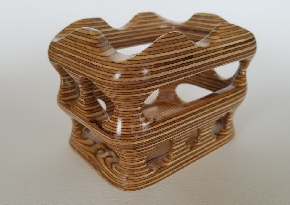
The picture above is of my first successful model created using this technique. It’s not meant to be anything specific but just a shape that would test the capabilities of this approach. At the end of this post is a more ambitious project I started that I still need to finish but better demonstrates the use to create an interesting shaped useful product.
A difficult part of the process is modeling a part that’s suitable for this process. The main issue to be aware of is that each layer shouldn’t have any undercuts unless you plan on flipping the stock over and machining both sides or have more machining capability that standard 3-axis milling. I wanted to limit my machining to a single side so I had to model the part so each layer has no undercuts, (all surfaces are either all sloping inwards or all sloping outwards). To do this, you also have to be aware of the layer thickness so that any change in slope direction happens at the layer transition. Here are some examples to better illustrate this.
The example below illustrates a simple case where the model on the left is the original solid. The picture in the center is the original model after it has been cut into slices where each slice is the thickness of the stock the pieces will be cut from. The picture on the right shows the slices laid out and ready for toolpath programming. The important thing to notice here is that all of the geometry that needs to be cut is accessible using a simple 3-axis CNC router.
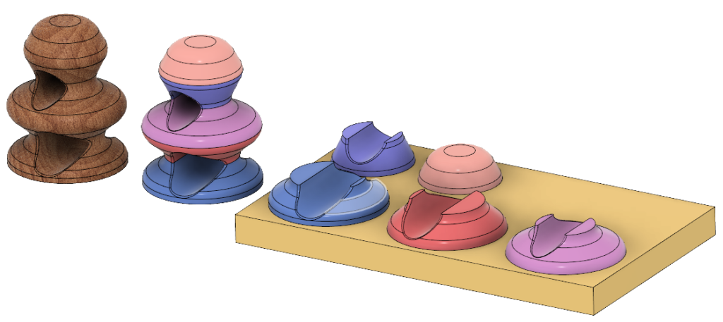
Below is another part that is more complex and begins to illustrate how this technique will allow you to create shapes using a 3-axis CNC router that wouldn’t typically be possible. This model has faces that slope in both directions, creating undercuts that can’t be cut with a simple 3-axis path. The important thing is that the angle of the part changes from a positive to negative slope at the slice transition. The second and fourth layers represent undercuts in the original model. However, those layers can be flipped over for machining so there are no undercuts. As you can see in the layout of the layers below, everything is accessible for a 3-axis path.
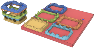
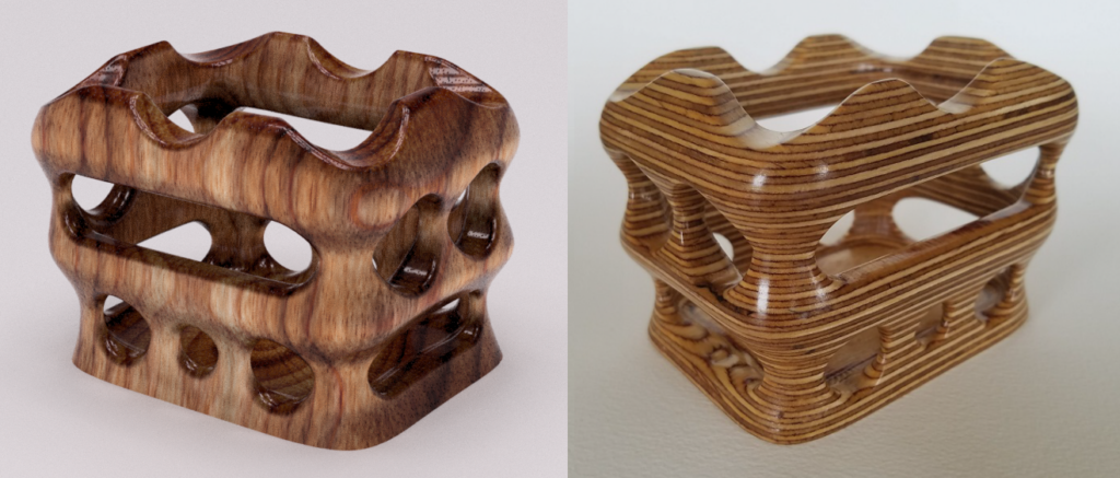
Here’s a more complex model that I created to test the process. The picture on the left is the original Fusion 360 model and the picture on the right is the physical part that I made using a sheet of Baltic birch plywood. The 3D wood appearances in Fusion 360 are great, but I wish there was a plywood appearance.
Below is the sliced model and the slices laid out on a board. See how there aren’t any undercuts in the laid out slices.
Here is a video of cutting one of the slices out. This is showing the finishing path using a ball-end mill in my Handibot CNC router.
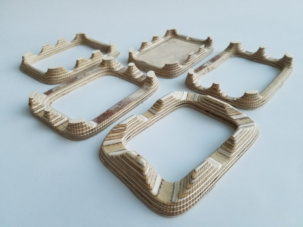
Here are the slices after machining.
And here it is with the slices stacked up.
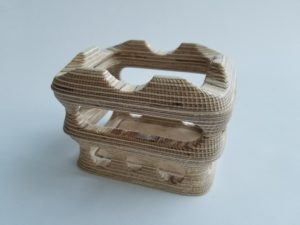
And now the finished piece after quite a bit of hand sanding and some oil-poly clear finish.
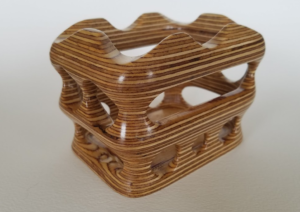
Creating a Model for Sub-Additive Manufacturing
The add-in, and what it does is conceptually fairly simple. The hard part is building a model that will result in slices that can be machined using 3-axis CNC. There are two basic rules when building the model; model relative to the slice thickness and avoid undercuts within each slice. The picture below helps to illustrate both of these concepts. It’s the previous model, where I’ve drawn lines to indicate the layer thickness, which is based on the board thickness. Within each layer, the angle of all of the faces either slope in or out.
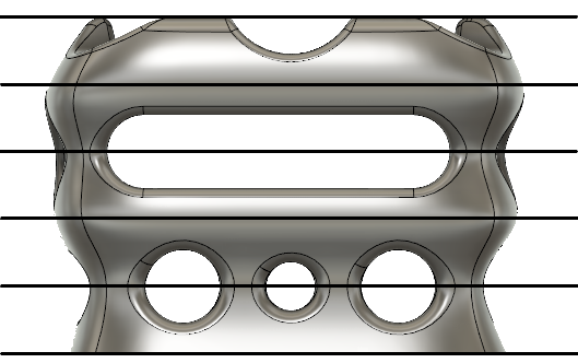
A couple of things I’ve done to help in creating a valid model is to first create construction planes that represent the boundary between each layer. You can then use construction planes for creating sketches and for visually checking to make sure the model is correct. Another technique is to draw a sketch with lines representing each layer so you end up with a picture like the one shown above. It serves as a visual check of the model. Any modeling technique can be used to create the model. It doesn’t matter how it was built or where it came from as long as the result can be sliced and machined. T-Spline models can also be used and they will allow for some interesting models but I have found it more difficult to control where the transition in the slope angle occurs. It also doesn’t have to be perfect because you can smooth out small issues when doing the final hand shaping and finishing.
Creating the Slices
Another part of the process that can be tedious is creating the slices to be machined, especially for larger projects like the one shown below that has 56 different pieces. I wrote a utility to help automate this step. You can get the Slice It Up utility on the Apps page. It creates new bodies that represent the slices of the original body and lays them out on the stock, flipping them as-needed to best avoid undercuts. It doesn’t do any intelligent nesting but just lays them out in a packed grid pattern where you can move and rotate them to manually nest them. This is easier than it sounds because you can drag them around with the mouse and use the MOVE/COPY command to rotate as needed.
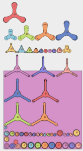
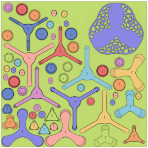
Here are the same parts, plus the top, manually nested onto a 4ft x 4ft board.
Bigger Project
Here’s a much bigger, and more daring, project that I have started. It’s modeled, all cut and mostly glued and shaped but still needs the final shaping and to be finished. Actually, I started this one before the little box above to use in a presentation I gave a few months ago at a local Fusion 360 meetup but it turned out to be a bit unrealistic to finish in the time frame I had. It still served the purpose of illustrating the process but needs to be finished. I did learn that it would have been better to spend more time machining to get a better finish than relying on the manual shaping at the end. Because of the size of this model, I’m using an angle grinder and rasps for some of the coarse shaping and then sandpaper for the final smoothing. I still have quite a bit of shaping and sanding to do but will post an update once it’s finished. One thing I learned with this model it that it’s difficult to get into the concave areas so it’s better to avoid them in the original model, when possible.
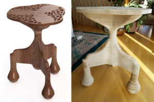
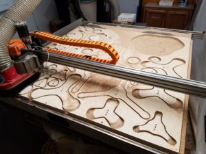
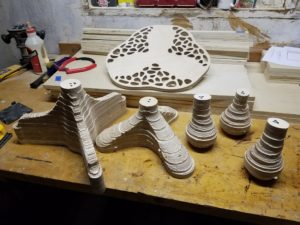
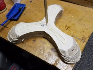
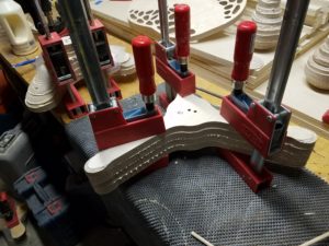
Below are some pictures of the process of cutting the parts and gluing them up. I was able to position all 56 parts in a 4 ft x 4 ft piece of Baltic birch. I added alignment holes to the original parts so I could use dowels to help align the pieces.
If you decide to create something using this technique or find another use for the Slice It Up add-in, please let me know. I’d like to see what ideas you have.


1 thought on “Sub-Additive Manufacturing”
I was pointed here by someone on the Autodesk forums. Great work. I too was disappointed by Slicer, and its limitation when it comes to 3D slicing